
Close
Nonlinear Dynamics in MEMS
Nonlinear Dynamics in MEMS resonators
People involved: V. Zega, A. Frangi
Numerical modelling of MicroElectroMechanical Systems (MEMS) resonators is attracting increasing interest from the sensors community especially when the nonlinear regime is activated by challenging applications of the device.
The dynamic response of a double-ended tuning fork MEMS resonator is studied both in the linear and nonlinear regime.
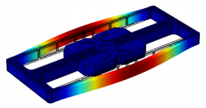
Figure 1: DETF MEMS resonator – first flexural mode. The contour of the displacement field is shown in color.
A one Degree Of Freedom (1 dof) model able to predict the frequency response of the device is proposed. Geometric and electrostatic nonlinearities are simulated through a Finite Element Method (FEM) and a Boundary Element Method (BEM) code, respectively. The total damping of the resonator is computed by taking into account both the thermoelastic and the nonlinear fluid contributions (http://intranet.dica.polimi.it/pub/fileadmin/user_upload/docenti_file/10069907/damping/damping.html). Experimental measurements performed on resonators fabricated in polysilicon and single crystal silicon validate the proposed model showing a very good agreement with theoretical predictions.
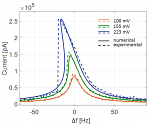
Figure 2: Frequency response of a DETF resonator. Numerical predictions and experimental measurements are reported in solid and dotted lines, respectively. The frequency responses correspond to a dc voltage of 3.6V on the mechanical structure and to different amplitudes of the time dependent signal on the driving electrodes: 100 mV, 155 mV and 223 mV. The pressure inside the package is assumed equal to 30 ubar.
[1] V. Zega, A. Frangi, G. Gattere, ‘Nonlinear Dynamics of MEMS resonators: numerical modelling and experiments’ IEEE Sensors 2019, Montreal, Canada, October 27-30, 2019.
[2] V. Zega, G. Gattere, S. Koppaka, A. Alter, G.D. Vukasin, A. Frangi, T.W. Kenny ‘Numerical modelling of Non-Linearities in MEMS resonators’ J. Microelectromech. Syst., 26(6), (2020), 1443-1453.
1:2 Internal resonance in a MEMS gyroscope test-structure
People involved: V. Zega, G. Gobat, A. Frangi
A numerical tool able to estimate a priori and in real-time the complex nonlinear responses of a MEMS gyroscope test-structure without resorting to simplified theories is proposed.
It predicts different working conditions without the need of ad-hoc calibration procedures.
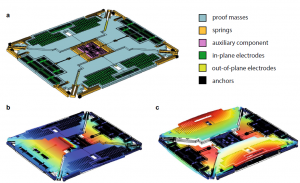
Figure 1: (a) Schematic view of the MEMS gyroscope test-structure. (b) Roll (f1 = 22,522 Hz) and (c) spurious roll (f2 = 43,386 Hz) modes. The contour plot of the displacement field is shown in color.
It consists in a nonlinear Model Order Reduction Technique based on the Implicit Static Condensation that allows to condense the high fidelity FEM models into few degrees of freedom, thus greatly speeding-up the solution phase and improving the design process of MEMS devices. In particular, the 1:2 internal resonance experienced in a MEMS gyroscope test-structure fabricated by STMicroelectronics is numerically investigated and an excellent agreement with experiments is found.
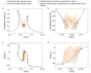
Figure 2: Frequency response of the MEMS gyroscope test-structure for a VAC = 3.16 mV and a VDC = 4.28 V in terms of (a) amplitude and (c) phase. Close-up views of the quasi-periodic region in the frequency response in terms of amplitude and phase are shown in (b)–(d). Numerical predictions are plotted with continuous blue lines, and experimental data with orange dashed lines. Stars mark theoretical Neimark–Sacker (dark blue) and Saddle–Node (red) bifurcations that delimit the quasi-periodic regime region and the unstable paths of the frequency response, respectively.
[1] G. Gobat, V. Zega, P. Fedeli, L. Guerinoni, C. Touzé, A. Frangi ‘Reduced order modelling and experimental validation of a MEMS gyroscope test-structure exhibiting 1:2 internal resonance’ Scientific Reports, 11 (1), (2021), 16390.