
Close
MEMS resonant accelerometers
The work is carried out in the framework of the collaboration of the department of Civil and Environmental Engineering of Politecnico di Milano, Italy with STMicroelectronics.
People involved: V. Zega, C. Comi, A. Corigliano, G. Langfelder
Dynamic response of torsional resonators
Torsional microresonators have applications in a number of microdevices, including gyroscopes and resonant accelerometers, magnetometers, mass detection devices and micro-mirrors. The study of torsional resonators, both in the linear and nonlinear ranges, is therefore needed in order to properly design such devices.
A mass of in-plane dimensions 2b × L and out-of-plane thickness t is connected to the device by two torsional springs which allow for its out-of-plane rotation θ(x, t) (counterclockwise positive). The mass is considered to be rigid while the deformable elements or ‘springs’ are thin beams of in-plane width s, out-of-plane thickness t and length l. Usually these springs are folded into n folds of length l/n in order to obtain a torsional stiffness lower than the bending stiffness. When in the rest position, the mass is at distance g0 from both electrodes on the substrate. The sensing electrode is usually connected to a virtual ground at zero voltage while the mass is kept at the polarization fixed voltage Vp. By applying a small variable voltage v(t) to the driving electrode the mass is electrostatically actuated and can dynamically vibrate according to its torsional mode.
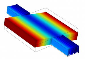
Figure 1: first mode of a MEMS torsional resonator. The contour of the displacement field is shown in colour.
The equations governing the torsional resonator dynamics can be obtained making use of Hamilton’s variational principle. The electrostatic moment exherted by the electrodes on the proof mass of the resonator induces nonlinearities and the dynamics of the resonator is well catched by a Duffing equation (1 degree of freedom approximation).
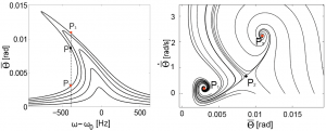
Figure 2: Dynamic response of the torsional resonator. a) Frequency-response curve with Vp = 6V and |v(t)|=10, 20, 30, 40, 50 mV; b) trajectories of the system in the state plane: the two stable steady state solutions (P1, P3) and the unstable one (P2) are marked with the red and black dots respectively.
[1] Caspani, C. Comi, A. Corigliano, G. Langfelder,V. Zega and S. Zerbini ‘Dynamic nonlinear behaviour of torsional resonators in MEMS’ Journal of Micromechanics and Microengineering, 24 (2014) 095025
[2] C. Comi, A. Corigliano, M. Doti, A. Garatti, G. Langfelder, V. Zega ‘Torsional microresonator in the nonlinear regime: experimental, numerical and analytical characterization’ Procedia Engineering, 168 (2016), 933-936
Out-of-plane resonant accelerometer
This device is characterized by differential resonant sensing, obtained from the variation of the electrostatic stiffness of two torsional resonators under the application of an external acceleration. The sensitivity, defined as the differential shift in resonance frequencies per gravity unit (lg = 9.8 m s–2), is of about 10 Hz/g when operated at a DC bias of 1.5V only. Over an acceleration range larger than 10 g, the deviation from linearity is lower than 1% and the cross-axis rejection is larger than 34 dB. The resonators temperature coefficients of frequency, in the order of –29 ppm °C–1, are matched within about 0.1%, resulting in linear offset drifts against temperature lower than 5 mg up to 95 °C in absence of any digital compensation.
The proposed accelerometer, is composed by a suspended, planar, perforated proof mass m of thickness s, connected to the substrate via a pair of 5-fold torsional springs, and by two torsional resonators. The two torsional elements can be kept in resonant oscillation according to their torsional natural mode by the driving electrodes located below them on the substrate. When in the rest position, the mass is nominally at distance g0 from both the electrodes and the torsional resonators have the same nominal frequency f0.
When an external out-of-plane acceleration is applied, the proof mass rotates and the gap between the resonators and the electrodes changes as shown in figure 3. In particular, a first resonator element approaches the substrate and its gap reduces to g0 – dβ while the other resonator element moves away from the same substrate and its gap increases to g0 + dβ, d being the distance between the symmetry axis and the rotation axis of the torsional resonator. Therefore, the electrostatic stiffness for resonators A and B changes. Combining the readout of the two frequencies fA and fB of the two torsional resonators, it is possible to measure the external acceleration applied to the device.
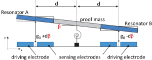
Figure 3: Schematic side view of the electrostatically actuated accelerometer, tilted under an external acceleration.
[1] C. Comi, A. Corigliano, G. Langfelder, V. Zega, S. Zerbini ‘Sensitivity and temperature behaviour of a novel zaxis differential resonant micro accelerometer’ Journal of Micromechanics and Microengineering 26 (2016) 1-11
[2] Caspani, C. Comi, A. Corigliano, G. Langfelder, V. Zega and S. Zerbini ‘A differential resonant micro accelerometer for out-of-plane measuremens’ Procedia Engineering, 87 (2014) 640-643
[3] C. Comi, A. Corigliano, V. Zega and S. Zerbini ‘Non linear response and optimization of a new z-axis resonant micro-accelerometer’ Mechatronics 40 (2016) 235-243